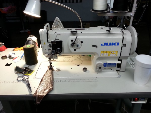
Juki DNU-1541S Sales Brochure.
These manuals are hard to find on the Internet. I found them.
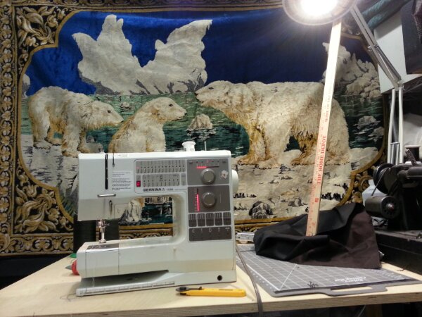
Bernina 1130 User Manual/Guide. PDF, 59 pages.
Bernina 1130/1120 Service Manual. PDF, 73 pages.
Keywords: Bernina 1130 User Manual. Bernina 1130 Repair. Bernina Oiling Guide. How to thread Bernina 1130. How to wind bobbin. How to lift presser foot. 1130 hook alignment.
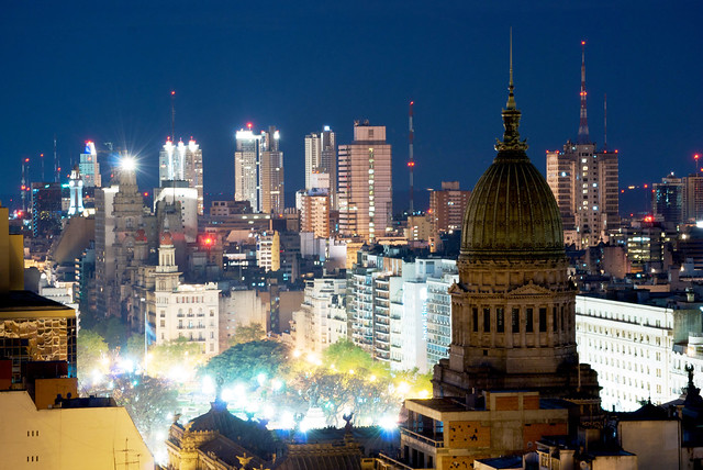
Faro de Palacio Barolo sobre Congreso (View of Buenos Aires and Palacio Barolo, at night) by Beatrice Murch, CC BY
I’m excited to announce that I’ll be giving talks in Buenos Aires and La Plata in the coming week. This is for the Creative Commons Global Summit:
The global community of Creative Commons will gather this year in Buenos Aires for our bi-annual Global Summit. The event, which will run for three days from 21 to 24 August, will be held at the Centro Cultural General San MartÃn and will be co-hosted by our local Creative Commons affiliates, Fundación VÃa Libre and Wikimedia Argentina. This is the first time the conference will be held in a Spanish-speaking country, and the second time in Latin America.
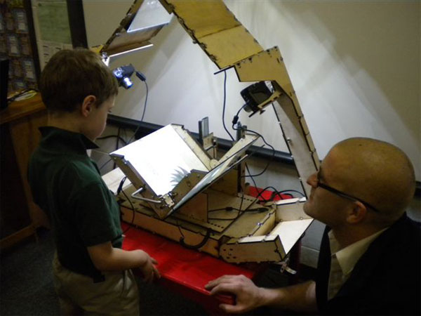
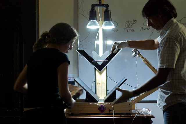
I’ve been working with Scann on this for almost a year now, and she’s been working hard behind the scenes to make it all happen. She’s been building scanners for use in Argentina by Wikimedia and other agencies, libraries, universities, projects. Here’s one of them:
I’ll be talking about the ways Open Hardware serves Open Content projects, and I’ll also be talking about how my project got started and where I see it going in the future. I’m so excited to go see the huge amount of work that’s been done in Argentina, and especially to learn from these users the ways that DIY Book Scanning can improve.
Sorry that this post is so short and so late – I’ve been preparing for days! Fortunately, there’s a lot more online…
Here it is! Big thanks to Dylan Love for doing a great job on the article.
“We are all in the gutter, but some of us are looking at the stars”
First Kathrine:
Then Daniel:
Article here:
http://newsstream.blogs.cnn.com/2011/04/14/saving-a-stranger-from-slavery/
I talked about what happened with Kseniya and Svetlana.
Thanks to Cory Charles for the opportunity.
So, uhh, I/my project made it into the print edition of the New York Times today, February 10th. Page C1 – Arts:
https://www.nytimes.com/2011/02/10/arts/10innovative.html?src=twrhp

I am proud to be called part of the “dark matter of innovation”.
I must correct one crucial fact – more than 250 people have built DIY Book Scanners – and I’m also aware of a whole shadow world of scanner builders who never join the forum and share (they show up on Craigslist and in other forums and websites every other day or so). My estimate on the total number of builds, documented and undocumented, completed and left unfinished, is between 350 and 500. DIYBookScanner.org (the site where the action happens) has been around for ~600 days, so that’s quite a few builds.
Well, hell. Life is good. The book scanner project is going gangbusters. We have not one, but two of the best open source book
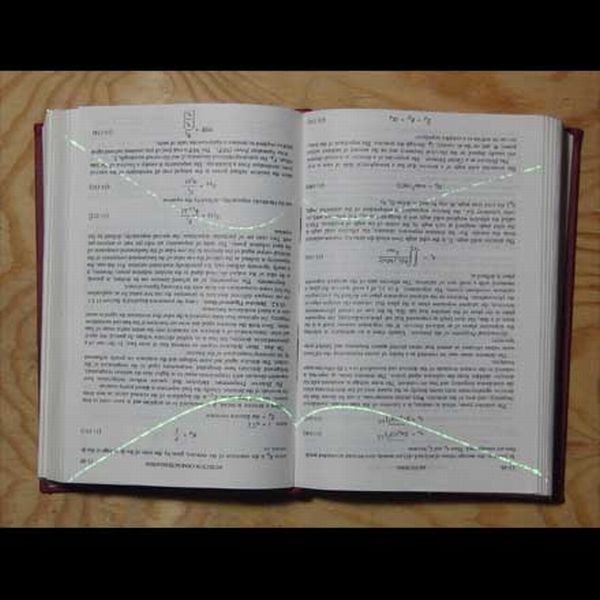
scanning applications out there (Scan Tailor and Book Scan Wizard, both GPL) which are being actively developed, improved, and community supported. Scan Tailor, in particular, has the best text-based dewarping ever implemented in free software. We have three community-developed open source ways to bind digital books (Bindery, DJVUBind, and PDFmaker), and we have a ton of hardware innovation going on. On the hardware front, we decided to try to see how little hardware we can use – so we’re co-developing hardware and software to use laser beams to “dewarp” (flatten) the images of book pages. Our first results came within hours of trying things out… and things look great. If this method reaches anything near the potential we’re seeing now, in the near future we could go from a $300 high speed book scanner made from trash to a $30 high speed book scanner made in the
USA – that fits in your handbag.
In the last year my community has helped out in Haiti, Africa, Canada, Indonesia, and all over the States. By “helped out” I mean offering advice, money, hardware, software, ongoing support, and even in-person meetups in Portland, OR (and elsewhere). We have substantial representation all over the world – particularly in Brazil (you should see these guys innovate), Germany (builders of auto page turners!), and Russia (a place where camera-based book scanning has been going on for over 40 years – the original DIY’ers). You can’t search for book scanning without finding us, because we’ve tried or seen almost everything out there, shared our experiences, and improved it as a collective effort. That said, sometimes finding what you want in our forums is a pain in the ass. I’m working on it.
As the founder and steward of this project, I often wonder how long book scanning will seem as important as it does now, in this pivotal moment of books gone bits. While once, I thought these thoughts cynically, I now think the same thoughts — differently. We are creating the future of personal document digitization, making it easy, free, and powerful — as it should be — and using things and skills that people already have. Someday, I hope, it will not be a big deal or seem so important, because it will be 1. freely available to anyone and 2. just a baseline expectation, like the free and simple use of printers and phone-cams is today.
Maybe I’m wrong. It’s hard to avoid such grandiose thoughts when you see a thousand people working together toward a common goal, each in their own way, on their own terms, in their own time, and according to their ever-rising ability. Maybe another technology will come along and disrupt our innovation, making things even easier, cheaper, faster, and more accessible.
I’d be glad to see that happen.
Thanks for your time.
Daniel
I love the Casio EX-FH100. I hate proprietary bullshit. It’s tremendously aggravating when a manufacturer arbitrarily makes up a new connector — especially when we have perfectly good standard connectors already. Proprietary bullshit stokes my rebel spirit, makes me fighty, makes me hack.
I know there’s plenty of interest in this information. I know because I, for one, was interested, and went looking. I found that people had discovered a few interesting things — among them that the remote for the F1 also works with the FH100. I also went asking for help from people close to the problem — and got zero response, which also aggravates the hell out of me. But I have a somewhat exaggerated ability to transmogrify aggravation into positive action. So action, it is. To be clear- this is no great hack. Rather, it is the inverse of a labor of love.
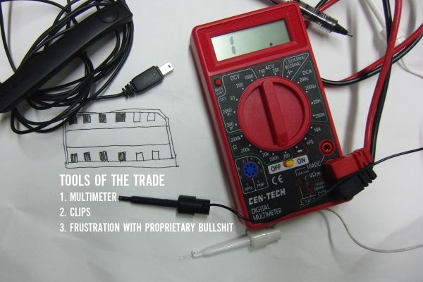
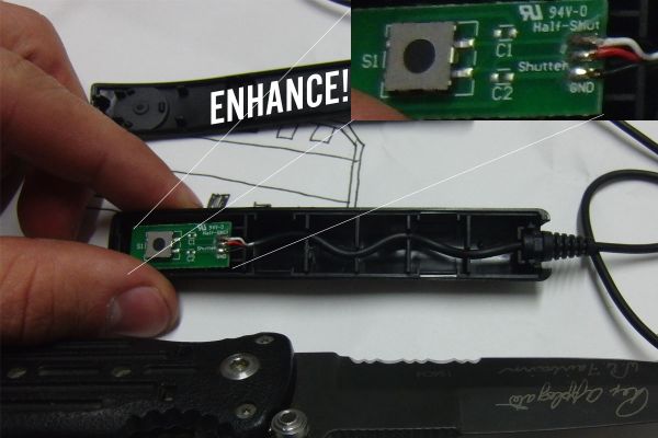
Gather your tools.
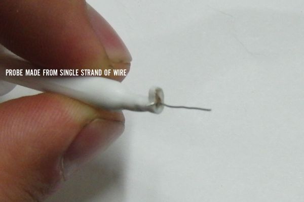
Make a micro-probe from a single strand of wire.
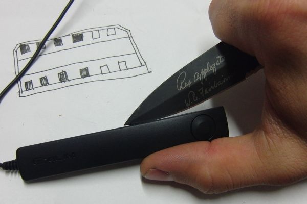
Get your fighting knife and cut in.
Check the silkscreen. Pinout:Half_Shut, Shutter, and GND. But we already knew that. How do they correspond to the pins on the connector?
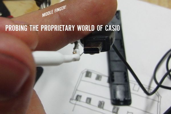
Probe it. Continuity between pins in the connector and traces on the circuit board, that’s what we’re lookin’ for.
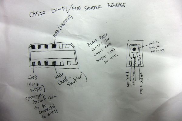
The shutter release cable:
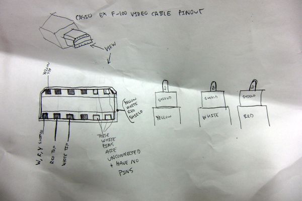
The video cable:
The USB cable:
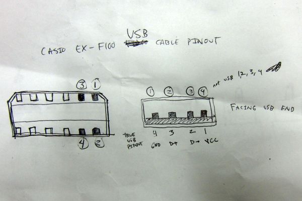
It is interesting that there are several pins which are not used in any of these three functions. I’d be surprised if they didn’t put the camera into some kind of service mode or something. Also, given that the pins are populated on the video cable, it seems possible to create a shutter release using that cable if you don’t have one, even though you’d probably have to cut all the way down to the connector to access those pins.
That’s all for now. Will cross-post this since it is camera related.
There are a bunch of higher-resolution images, including images of the EX-F1 and EX-FH100 connector here.
I’m pleased to say that the NYT made mention of my community and my recent article today.
I’m also pleased to announce that technology that I’ve developed with that community will be helping improve the lives of people in Haiti:
The DIY Book Scanner community, partnering with LeaveALittleRoom and Renewal4Haiti, has come together to help Camejo Hospital in Léogâne. This is the prototype scanner we built, before it was painted and sent off for further development:

From DonnaA, the project representative in the forums and founder of Leave A Little Room:

Camejo Hospital is in Léogâne, Haiti — epicenter of the Jan2010 earthquake and the site of Hurricane Tomas landfall. Dr Joe and Dr Cam are a married Haitian couple who have been medical doctors in this region for over 20 years. (I know their adult son, Jodel, a software engineer who lives in Colorado with his wife, Sue, who is a nurse.) They have about 80,000 handwritten records of their patients in this region, indexed by a patient ID number. While Dr Joe and Dr Cam are rebuilding the hospital that was destroyed in the earthquake (see renewal4haiti.com for details), operating in a temporary clinic and their currently-flooded family clinic, they are also very interested in converting their patient records into a digital database. We are setting up an open source database for them and considering how to bring their handwritten records into that infrastructure. It’s an opportunity to leapfrog to current technology for their medical records, investing in the asset of historical public health information that they have created during their 20+ years of service.

The records are kept in “copy books”; when closed, these resemble large scrapbook/photo albums. They are approximately 10″ x 18″ with varying thickness. Blank copy books are made at a local bindery. The index that maps a patient ID number to the patient name is kept in a spiral-bound notebook. Entries are in pen — black or blue ink — in cursive handwriting, in French. In the patient exam copy books, there are typically five columns drawn on a blank copy book page; each column is used for one patient during the time that this copy book is active, accommodating multiple visits. Entries are made on both sides of each sheet of paper in the copy book. Entries in the lab copy books are structured somewhat differently than entries in the patient exam copy books. Lab information is transferred from the lab copy book to the patient exam copy book.

The hospital temporary clinic and the family clinic have electricity available sometimes. At the family clinic, electricity is available from a local utility an hour or two some days, and no electricity at all on other days. At the hospital temporary clinic, located at the site where the hospital stood pre-earthquake, there is no electricity infrastructure, but there is a generator that is run a couple of times each day to recharge an array of batteries. This location will eventually have a solar electricity system that is being designed to meet 100% of its electricity needs; installation will be incremental. Our book scanner must be useable in this environment of occasional electricity, without depriving the clinic of scarce electricity needed to provide patient care.
Thanks, DonnaA for your work and for getting us all started on this project. This isn’t the first time DIY Book Scanner technology has been used to scan the medical records of people in bad situations (it’s also been used in Africa) but it is the first time that we’ve been able to publicly work together to better the lives of people who are working to help themselves.
That is our skill — helping people develop technology to help themselves. We’re grateful for the opportunity.

Today, Google announced the availability of their ebook store. Times, they are changin’…
Today, I proud to announce that my article “The Why in DIY Book Scanning” is now available [PDF] from New York Law School Review. In it, I tell the story of the DIY Book Scanning community and make an argument for why people should scan their own books, even when services like Google eBooks exist.
I am grateful to James Grimmelmann for well, a lot of things, to Noah Bicknell for helping me at every stage of writing, and to the editors for their insightful comments, patience, and hard work in bringing this article to press.
The original book scanner plans took the grand prize in the Instructables/Epilog Grand Challenge. The grand prize was a laser cutter — and the moment I got the laser cutter I started using it to make more book scanners. In a future ostensibly full of such rapid prototyping machines, we should be able to simply “print” a book scanner from wood or plastic. This scanner design is more or less a tech demo showing it can be done.
I promised I’d release the artwork to produce one of these scanners last October, but haven’t had the time. That’s where Dário de Moura comes in. He had been working on a 3D model of the folding scanner from the photographs I’d shared. I sent him all the original artwork to work from, as well. We have been working on a GPL release of the so-called “3rd Generation” laser-cut book scanner for some months now. Dário has done the lion’s share of the work, having sorted through the mess of Corel artwork, created perfect Sketchup models and a bunch of documentation.

This is only a preview of the scanner. Do not use this artwork to produce anything just yet. Do not post it on another website just yet. We have some details to work out (file naming, proper credits, alternate formats) and we have some GPL licensing issues to work out as well. That said, as promised, you can download these files now and see the work we’ve been doing. Over the next few weeks, we will be releasing a beta of the scanner with more complete licensing information, credits, etc. It will be Free, in any case.
The Parts List (neatly shows the placement of each part)
http://www.diybookscanner.org/Dan_and_Dario_Scanner/Bookscanner_V3-PartList.pdf
The Manual (Describes each section/view of the scanner)
http://www.diybookscanner.org/Dan_and_Dario_Scanner/Manual_V3.pdf
The Sketchup Artwork:
http://www.diybookscanner.org/Dan_and_Dario_Scanner/Bookscanner_v3.zip
The Electronics Package:
http://www.diybookscanner.org/Dan_and_Dario_Scanner/Bookscanner%20v3_electronics.pdf
Guest: Daniel Reetz, founder and steward of the DIY Book Scanner community
Where: MIT Media Lab E14-240
When: Wednesday March 24, 2010 14:00-15:30
Hope to see you there. Special thanks: Mako.
I’m totally excited about my upcoming speaking engagement at Harvard’s Berkman Center. So excited, in fact, that I’m going to use the opportunity to announce the release of a few new, exciting projects from the forums here. It’s going to be an exciting talk and I can hardly wait to engage with people in Cambridge.
DETAILS:
Tuesday, March 23, 12:30 pm
Berkman Center, 23 Everett Street, second floor
RSVP required for those attending in person (rsvp@cyber.law.harvard.edu)
This event will be webcast live at 12:30 pm ET and archived on our site shortly after.
The official announcement is here.
If you want to meet up, get in touch.
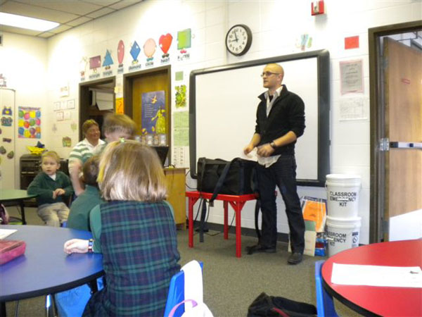
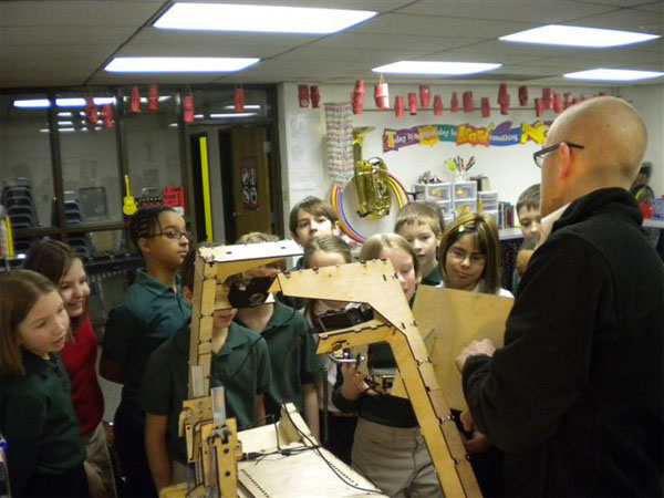
My nephew asked me to be his show-and-tell a few weeks ago. I finally made time to visit him today. The visit was a total success. I presented the DIY Book Scanner project to kindergarteners, 4th graders, and 5th graders.
I kept the scanner in its bag, and asked the class for help unpacking it.
The response was pretty enthusiastic. 😉
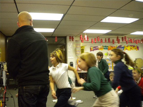
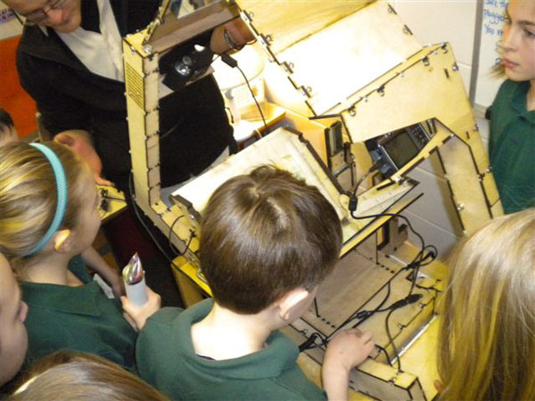
Every student got to scan a page from a book. This was Sendak’s Where The Wild Things Are.
The 4th graders were super-attentive. They got the idea of book freedom and scanner utility immediately. They asked great questions, including my favorite (“Have you ever made any stuff that was a mistake or didn’t work?”) — I answered, explaining that I was actually showing them the three or four successes I’ve had among hundreds of failures. They got it, immediately.
More. Look at those smiles.
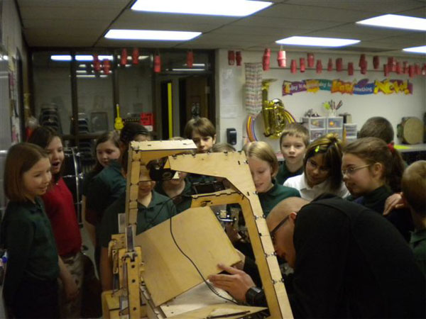
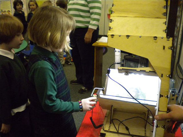
The best thing was having them help handle and assemble the machine. They were totally fascinated with the laser-cut wood, understood that the camera control was something special, and were able to operate the scanner immediately.
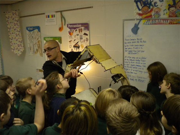
Hands-on. The only way to show the scanner.
And Ben in front of the scanner. Thanks for inviting me, Ben. I had a great time. Can’t wait to go to Surplus with you this afternoon.
And thanks to Sarah, for having me, and for taking these pictures.
I’ve been modifying radios, scanners, and mobile phones for years. I’ve learned from experience that these industries are total bastards when it comes to connectors and pinouts. More often than not, the connector on any mobile device, including phones, is some proprietary one-off thing, even when the protocol is almost invariably serial. This goes double for scanners, communications receivers, and pagers. Hell, even GPS units have bizarro connectors. Connectors so badly designed and outrageously expensive that most people just made their own.
These are the sorts of things that are only justifiable to businessmen — Yes! make a one-of-a-kind undocumented connector, and then charge loads of money for cables and connectors, because we’re the only source! You can almost hear them laughing all the way to the bank extinction.
I recently acquired a Uniden Bearcat BCD396XT, which is a remarkable radio. The most salient feature of this radio is its ability to decode APCO25-standard broadcasts, which now comprise the majority of public service frequencies like police, fire, etc. But this radio goes a step further, allowing connection to a GPS (for “location based scanning”, a funny thing for a radio device, when radio was invented to overcome problems of distance) or to a computer for complete control. Problem is, the connector of interest is wacky.
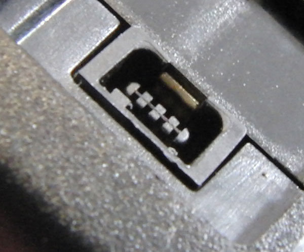
This connector, though it kinda resembles USB connectors, does not transport a USB signal. It is a plain old serial connection. Why they chose to use this connector is beyond me. However, as a hacker, I want access to those pins. I could just open the radio and solder to the board, but it’s more elegant and flexible to find the connectors themselves. After taking some detailed photographs, and searching around a bit, I was able to find a replacement.
Detailed photographs:
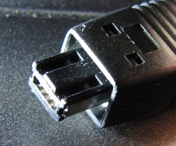
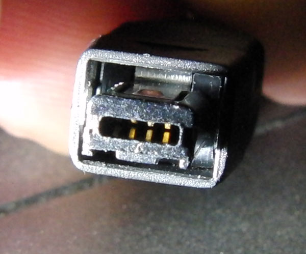
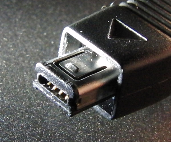
Items on eBay — they can be had for about a dollar each, with shipping — a hell of a lot cheaper than the $20 asking price for the standard serial cable. The magic search words turned out to be “4 pin mini USB cable” (most are 5 pin, these 4 pin models appear on a few odd digital cameras and MP3 players).
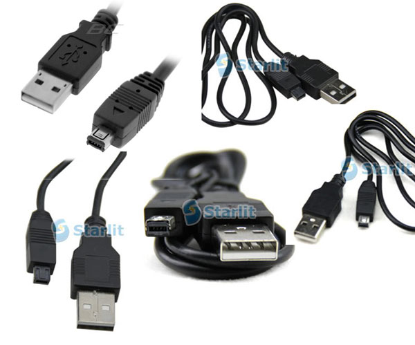
Please note, these cables are only good for the connectors on the end. Plugging the radio into a USB port without a proper USB adapter is asking for pain.
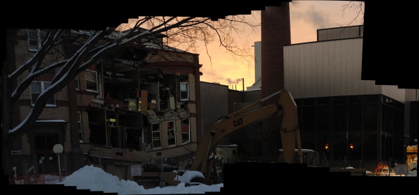
NDSU posted some official information about the collapse, though of course the back-channel email communication is far more interesting. I made an animation from their webcam images.
Note particularly the steam in the stairwell — the steam heat in the building might have flooded the building with a wet, hot cloud.
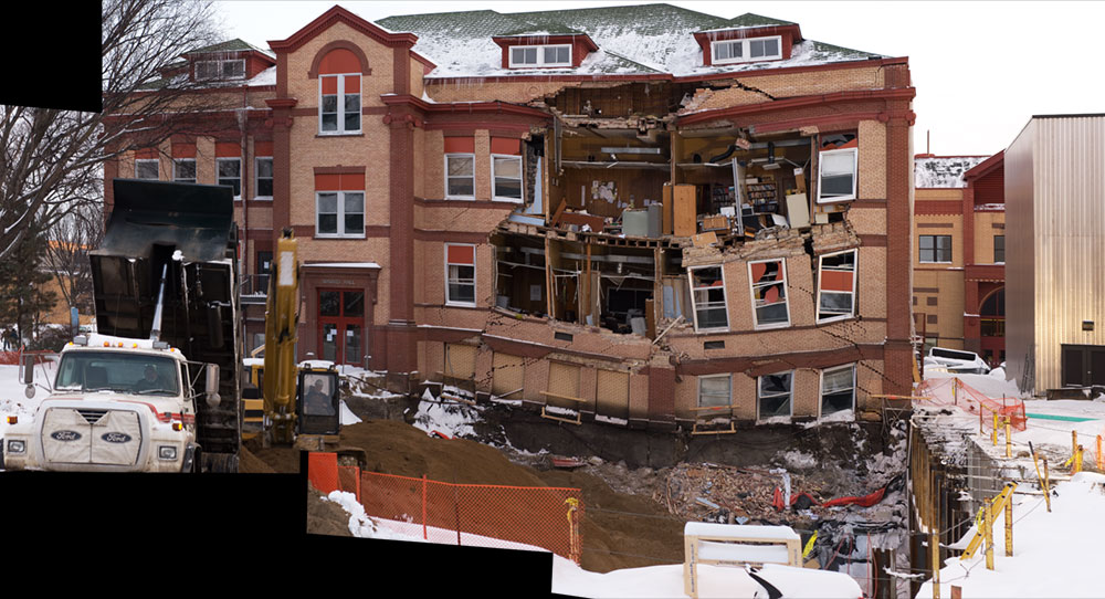
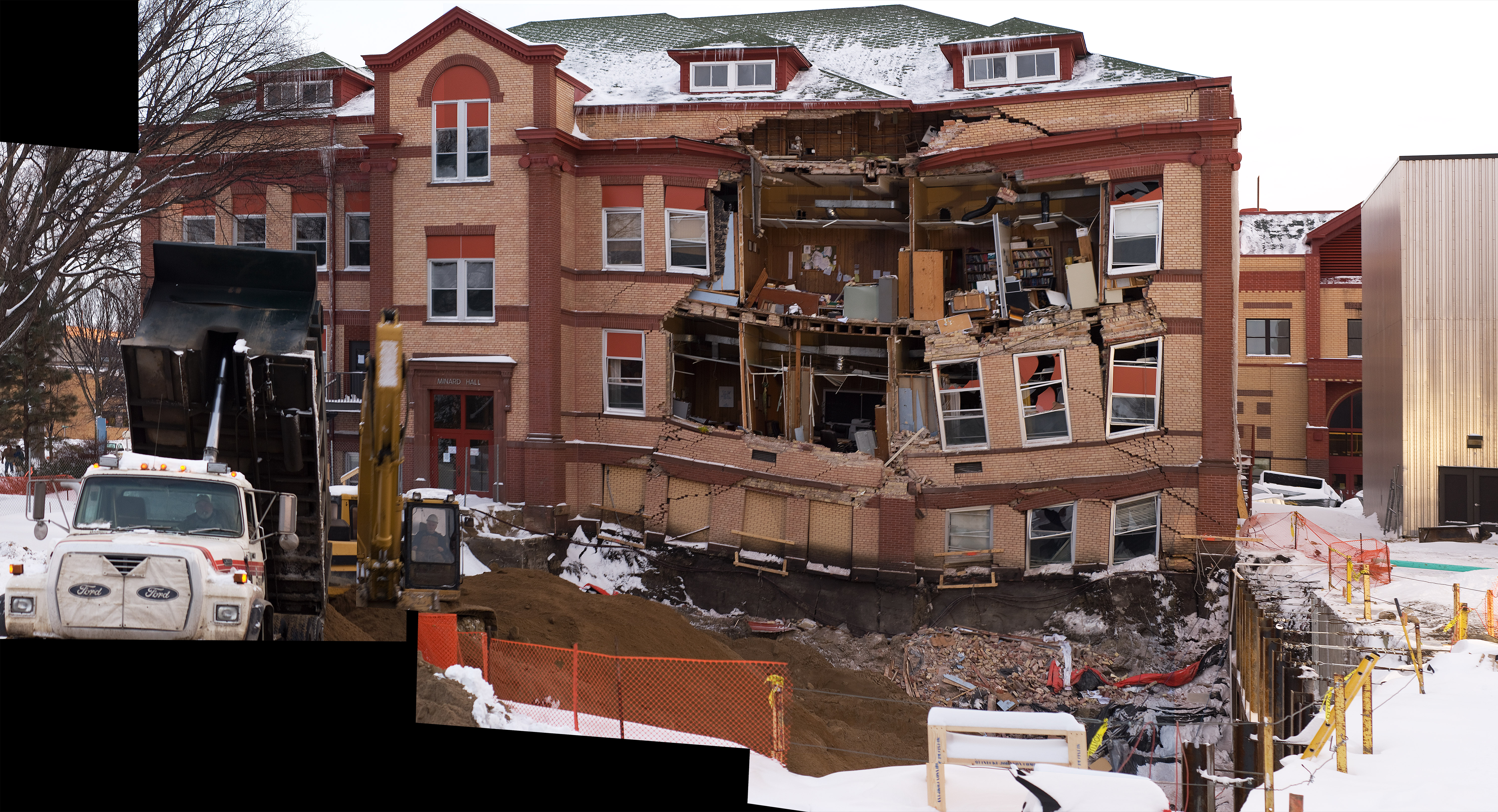
Photosynth is a “Photo Tourism” application that lets you seamlessly navigate all 728 high resolution images I took of the Minard Hall collapse.
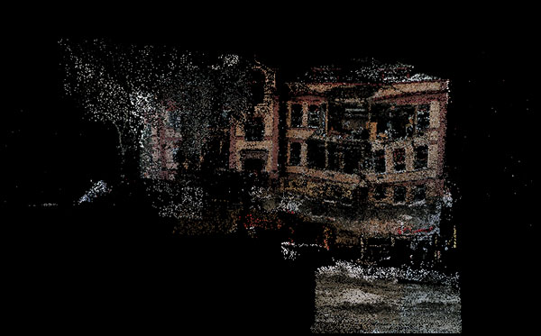
Requires Microsoft Silverlight, sorry.
Before:
After:
Instructables.com has announced their “Best of 2009” winners and the DIY Book Scanner Instructable was in the top ten in the category “Most Viewed”.
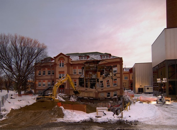
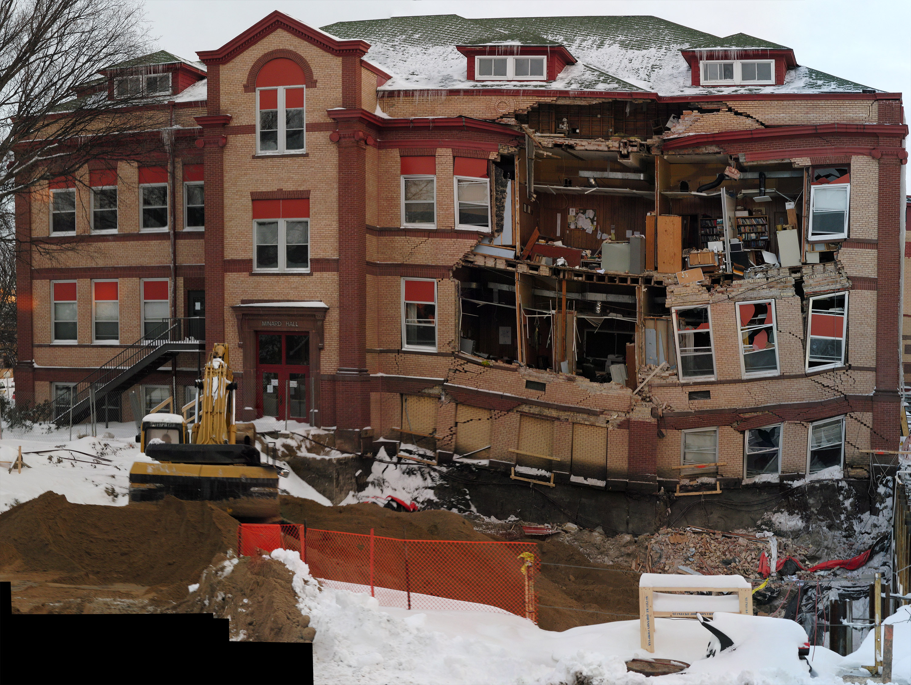
Recent construction-related excavation work on Minard Hall caused the North face of the building to collapse, exposing faculty offices and engineering incompetence in one fell swoop.
Minard Hall (formerly Science Hall) has a concrete foundation which rests on a bed of smectite clay. This clay, the main ingredient in clumping kitty litter, is the “bedrock” of Fargo, North Dakota and much of the Red River Valley. You might think of Fargo as a bit of frozen cat crap shifting around an enormous bed of saturated litter. To prevent catastrophic collapse, heavy buildings in the area are usually placed on 150 foot caissons (stilts), which rest on bedrock. Because Minard rests on the clay alone, removing the surrounding dirt probably caused the clay to ooze from underneath the building. More about smectite clays from Dr. Donald Schwert, who has precisely nothing to do with this post.
Larger.
Larger still (86.9 megapixels, 11mb).
Unfortunately, this building houses my department, experiment, and student office.
In this image, the third window from the bottom right is my office.
Larger.
Larger still.

Larger.
Larger still (82 megapixels, 10mb).

Larger.
Larger still (19.5 megapixels).
This collapse represents a major setback for the institution as a whole, not to mention my progress as a graduate student. Tough times.